Check out my YouTube Channel: Power Operational Intelligence
Now Live! Overview, Structure, Task Data, Table Design, SQL Server, and Re-Linking now showing.
Video courses covering material on this website, and more, are presented in the playlists.
Code snippet links at YouTube Code Snippets. Twitter at @poweroperation1, #poweropi, #poweroperationalintelligence.
Subscribe on YouTube, and click the "Notification" Bell icon to be notified as content is published.
Collected PowerOpI Posts on Silicon Valley Project Management

Program RoadmapRichard Bixler Summary: Design The Path of the Program Effort. Some Programs work fine without a Program Plan. Many Programs perform well by using a Program Plan. And there are classes of Program that NEED a Program Plan. Why would a PM build and use a Program Plan? Isn't that fixed and bureaucratic? Isn't that "not Agile"? Isn't it more Agile, and better, to be #NoEstimates? After all, Individuals and Interactions Over Processes and Tools; Working Software Over Comprehensive Documentation; Responding to Change Over Following a Plan... Well, that's great for a class of programs. But program size, complexity and technology, as well as organizational and financial reality, often require planning to be successful. So, what if a Program Plan can be operational instead of fixed, can coordinate collaboration, is responsive to change, communicating and coordinating implementation! A properly-constructed plan can make it possible to do all that: It can be Agile, handling change as it comes and based on instantaneous reality, scaling to program size, using automation to control planning effort, and handling multiple operational environments even within a single Program. This article is about creating and using such a plan. Published simultaneously on svprojectmanagement. Universal Constants for Program Management
... or can you? Sometimes that would be more than nice. Coupling effective planning and execution give your Program powerful methodology effective in avoiding and overcoming hard problems that result from these and other universal constants. Considering a Program PlanWhy Wouldn't You Want a Program Plan?I hear all these reasons to not create and use a Program plan:
Why Could A Program Benefit From a Plan?"If you don't know where you are going, you'll end up someplace else." - Yogi Berra A well-publicized plan identifying critical-path tasks and kept up-to-date in real time, provides a quantified mechanism:
A plan can create visibility that
Planning and executing are an opportunity to assert valuable PM presence and to provide leadership. These make visible responsibility and accountability of Program Management, and then throughout the organization. Cost/Benefit Analysis of a Program PlanI respect these ideas within their un-stated scope. But some Programs, as a whole, or in some elements within a Program, may find that a plan is useful, effective, advisable, even necessary for success. This is the case for complex or large projects, particularly but not exclusively including physical/hardware elements.
In the end the value of a Program Plan depends on a Cost/Benefit tradeoff: Is the cost of developing and using a Program Plan, in money, effort and time, a net benefit, or is it a net cost or impediment to the Program? What characteristics drive need for planning a Program?
Statistics are that a large majority of projects fail... How Agile is a project that fails? Thinking through how to translate a concept into shippable reality, building a plan for that, built-in to be adaptable and capable of accepting and implementing change, then actively USING the plan to achieve success... Maybe that's a good business plan after all, and Agile besides! Promote AgilityAgility still applies to these programsThe primary role of Program Management is to manage and deliver a complex, perhaps large, program to meet its constraints which include revenue date and program financial spending amounts and timing. Regarding agility, it is not necessarily PM intent to implement scrum in a prescribed manner, although the program may adopt that in whole or in part within an organizational custom. However, it can be PM intent to implement an agile mindset: Changes to product and program are inevitable during the course of the program, so the program must be able to be able to accept and incorporate change whether it affects a part of the program following scrum practices, or a part constrained by dependencies, sequences, time and finance. Hardware development physics and logistics are different than for software development in many ways. Many of the factors are described in this article, and also described in others listed for further reading below. Nevertheless, important aspects of Agile can be productively applied to hardware development, described in this article and by the further reading articles. For reference, a series from another source also discusses Applying agile to hardware development. Agility implies acceptance of change, and also real ability to incorporate change, all based on current conditions. It goes without saying that incorporating change should maintain or even improve business from the Program, rather than to degrade it. "No Plan" during execution, particularly of large or complex Programs, may lead to chaos managing change. Numerous project elements developed in parallel with mutual dependencies on sequence, availability, resource and funding, each contribute to both logistical and technical complexity. Ad-hoc management of change to these projects can be a challenge. You don't just make a plan and then store it in a corner. And, having a plan doesn't mean your project can just "turn the crank" and be successful. The world may change, or the plan may be wrong or incomplete. A plan is initially "due diligence" to tangibly support asserted business success of a proposal - "best known path from here". Then, the Plan becomes increasingly accurate as it is updated with actuals, as well as over time as constraint uncertainties are refined, and as tasks are completed, removing contributors to uncertainty in upcoming work. A plan updated with change may provide coordinated direction to specific processes and organizations to incorporate the intended change. Also, recording of such a plan on completion may provide organizational learning leverage to subsequent programs, on program structure and practices, timing and cost. Common practices in System Development that support Agility and Agile methodology Modular Architecture: Hardware, and related software (firmware, drivers, management) are inherently modular, separated by interconnect physical and logical interfaces. This allows for parallel independent workflow. This article describes decomposition of a Program into several parallel Integration Cycles, with stated expectations on modules and organizational operation. Expectations include incoming and outgoing functionalities, with dates needed to coordinate integrations among system modules and organizational processes. This top-level Program structure allows each module development effort to choose its local methodology within the stated expectations, allowing substantial self-determination by developers, and balanced to support business needs on cost, operation, and timing. Dependency Inversion: As design progresses, system entities become progressively abstracted: Architecture/Design (Function, Partition, Interconnect, Physical) -> Boards, Drivers -> Assemblies/Chassis/Platform -> System. Interactions among these are typically well-defined. Modern hardware design is largely controlled by firmware with an element-level management processor, which can set chip configuration control values via control pins, messaging, or training operation. The firmware is connected via API or messaging, allowing separate management operations to configure and control low-level configuration and operation. Dependency Elimination: Scrum methodology advocates elimination of dependencies, and many of the items identified in this section are means to do so. Dependency elimination is sometimes achieved by broadening scope of a Scrum team to cover development that would otherwise have been a dependency from outside that team. That is not always possible, and may create awkward focus to the team. But there is another way: Planning, including identification of dependencies, far enough in advance that required work is completed before the work product would become a critical dependency. SAFe methodology provides Program Increment planning that plans out upcoming dependencies in shortly-upcoming work. PI planning doesn't include dependency task duration so sequencing is approximate. So PI can be a partial solution, whether or not full SAFe methodology is employed. For system work, the GANTT developed early in the Program, and updated throughout reflecting realities with increasing accuracy, identifies task dependencies with duration (at least approximate), so delivery sequencing and time can be planned. The GANTT methodology can provide complete elimination by planning and positioning work ahead to be completed before it becomes a time-critical dependency. The GANTT methodology requires work up-front and continual update. But it very reliably identifies dependencies and can be used to either eliminate or at least directly manage them, providing the best known way to optimize workflow. Continuous Integration: Repeated, iterative Integration Cycles integrate changes and additions, abstract them, and provide for escalation of testing along the routes of abstraction (board-level, assembly-level, chassis-level, system-level). Each level of test persists throughout the development effort, and each Integration Cycle inherits test and change results from prior Cycles. Feature Toggles: Modularity facilitates separation and function toggle, so much system debug can be done on live systems. However an anti-pattern exists: system elements operate at a low level in the system, and can require invasive interaction (crash, re-boot, power cycle) and initiate errors that can be fatal to system operation. Also, some system test must occur in hostile environments and may be tested to failure. The anti-pattern can be avoided by performing these tests on systems separate from other development efforts. Team Development: System elements (hardware and associated software) are inherently cross-functional efforts (EE and ME, Driver, Supply Chain, Manufacturing, Firmware, System function, Test) driving constant review among team members. Dependencies in this environment are inevitable, but common practice, including capabilities discussed in this article, facilitate identification and management of dependencies among system elements. The Program structure described in this article does not mandate Agile team structure or any other team structure. Team structures and methodologies are likely to be mixed in a system development program; the requirement is to meet the agreed Integration Sequence functionality and timing. The best team structures match their work content. If there were a preferred team structure, it would emphasize personal responsibility and initiative and would eschew bureaucracy and group-think. Other articles in this sequence describe programs built as a hierarchy of focused teams organized around functional product elements or sub-groupings of functionality, with dev technical leadership, and coordinated by agreed details of the Program Plan. Focused teams are small, coordinating on their own focus and dependencies by communication and planning rather than by broadening team content. Communication is transparent and covers short-term work and position in the longer-term, and is relevant to each sub-team. This is accomplished based on data integrated among sub-teams and communicated using data and images. These are illustrated below. People love working in a focused team when related teams competently provide deliverables in well-coordinated fashion. Version Control: System development Programs are usually large and complex, requiring version control throughout. Hardware elements operate within strict version control systems for hardware design (Verilog) and hardware entity builds (BOM, build plan). Driver and firmware inevitably work within private “development" branches prior to integration into system branch and release branch. In short, version control and branch management are commonly well-defined for system efforts. API-First: Because of modular separation, physical interfaces are usually standards-based buses and serial links. These may embody several instances, but because they are adopted by customers, they are usually well-documented. Functional separation via driver interface to systems typically uses standard structures such as REST, SOAP, GraphQL, XML-RPC etc. In the preferred Program Plan described in this article, infrastructure of the product is developed right up front in the Initial Design Sequence. This includes APIs along with architecture, function partitioning, interconnect, messaging, data structures, libraries etc. These are done early rather than throughout the Program, to avoid popping up asynchronously later, thereby limiting dependencies and allowing product function and feature development to use them without dependency. Messaging Interface: Modern system-element design above chip-level is typically controlled by firmware and software, using message-based command verbs. Functions may depend on each other, but substitution of function from other sources (prior systems, commercial product) may be used to postpone direct dependency and separate integration and debug efforts. Documentation: Because low-level system elements are typically designed among numerous partners (chip-supplier, board fab, standard interfaces and APIs, system designers, supply chain and Manufacturing Operations, plug-in suppliers, and PM logistics plans and Program Plan discussed in this article), numerous instances of documentation are common. These plans may also inform other program efforts operating in parallel, or archived plans can provide history informing subsequent program efforts. Agility Through AutomationComplexity of a program is inevitably reflected in a Program Plan. Complexity may be due to details of its technologies, to program size, or to organizational complexities such as dependencies, locations or diversity of specializations. These are often characteristics of programs handling physical materials (computer hardware, civil construction) but could apply to software programs as well particularly if they span software application technologies, or broad global development or product distribution. Such complexity has historically required onerous effort to plan and manage change, with the result that plans may remain inflexible if not inaccurate. But it is quite possible to build a plan in such a way that a computer can do the hard work. This allows us to keep the plan up-to-date, reflecting current realities, incorporating change, and quickly able to communicate among organizations and individuals to coordinate tasks, priorities, outlooks and financials. Using this methodology, a program can accept and assess change, then coordinate, incorporate and execute change with agility. A section below describes description of the Program plan as tables that can be JOINed, and QUERIED for reports and illustration, and communicated throughout the Program - using computer power to update and propagate change quickly and with minimized effort. Just takes some methodology and data design up front, which can also be leveraged repeatedly into subsequent Programs. In addition to reducing work to plan change throughout the product and organization, a plan incorporating automated update may avoid planning mistakes and omissions, propagating change correctly among multiple repeated instances. Eliminating mistakes should also be an Agile consideration! Build the Plan
What would a Program Plan look like? Following, illustration of a development plan for a system element (Compute, Storage, Network) and systems used for internal test, and as Reference Systems illustrating/specifying customer-environment configurations. Principles may apply to a broad range of Program types. Summary of Planning ApproachRemember the advice from my article on PM Skills: When confronted by a big problem, break it down. It's never all-or-nothing. Planning inherently breaks down a complex work effort into chunks manageable over time and among multiple organizational, process and project elements.
Initial Design SequenceA Program is typically formally initiated by a business proposal, usually driven by the market-oriented Product Management organization. The business proposal includes market concept and explicit product positioning and key features, with high-level estimates of development duration, cost, and NPV/ROI from Program Management. Once the proposal is accepted, work begins on initial development work, in parallel with full Program planning. Much design work for product core structural hardware and software platform design occurs at the start of the program, even if design continues through the duration of the program. The following steps for core hardware and software design steps sketch out system-level programs. Even though other programs may differ substantially, I would expect a program to develop some sequential intent at least analogous to these steps. Technical management of design work is generally led by DevLeads and Scrum Leads et al., more than by Program Manager. Design work, and Test work are usually intangible and duration is difficult to estimate. I use TimeBoxing to allocate a block of time approximately adequate based on prior program actuals. For a program of the type and size of my examples here I use 6-months of design work described just below, followed by 3-months of physical design (layout, build drawings) with continued parallel design work. This 9-month block is followed directly by iterative/parallel/sequential Integration Cycles described below to build, integrate and test hardware/firmware/software prototypes, to further develop function and add-ins, and to develop production and support capabilities. These lead to production and shipment to customers. Hardware: Much design is done before first build and integration steps, with corner and margin testing, testing scalability and stability, compliance, and regulatory following later in the program. Hardware early design work includes but is not limited to:
Software: development is usually more open-ended than for hardware, with design extending through much of the life of the program. SQA and branch management are introduced, then bug triage, leading to release candidate. Developing a good block structure of intended software and hardware development modules right up front helps break down the large problem into smaller executable pieces.
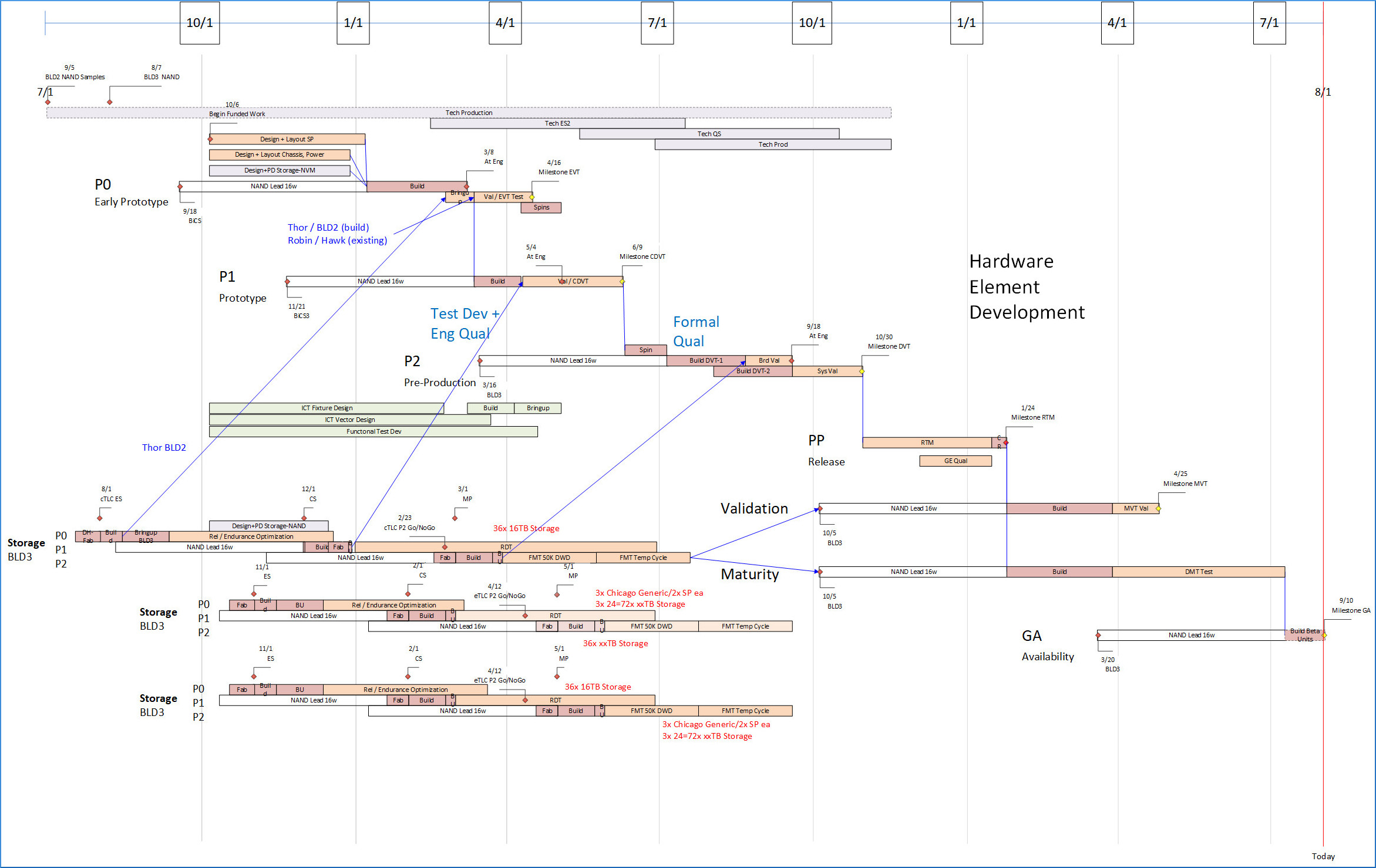
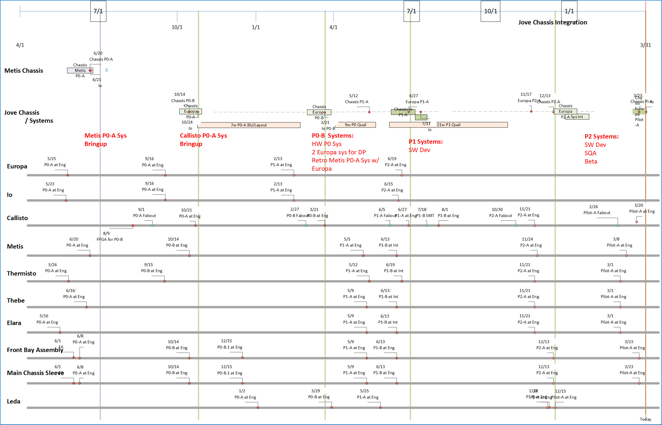
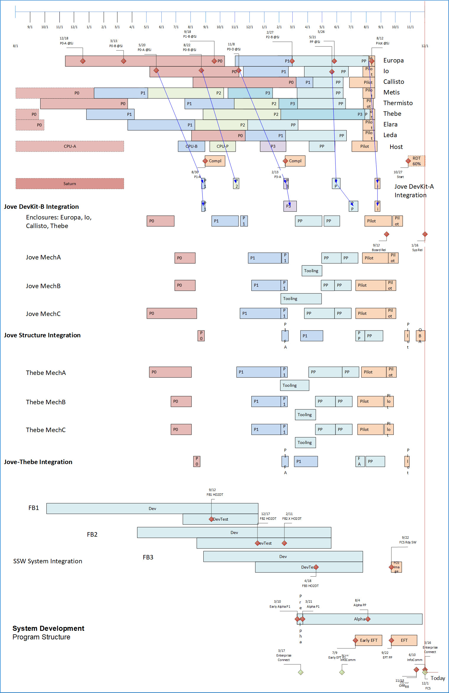
These pieces are next woven together into a small-fixed-number of major integraton steps of hardware and software functionality, leading from early development through broader development then readiness for production and release to commercial use, and subsequent enhancement/bugfix releases. Develop Integration Sequences Around Integration PointsAssert Project major structure involving sequencing, and aligning major dependencies. Build buy-in throughout the organization, management, and adjacent functions, on product structure, sequencing, development and validation plan. Assert key milestones and sequences. It's useful to focus on Integration Points, within longer Integration Sequences. An Integration Sequence typically includes operations for Material Acquisition (PO, distributor, lead-time); Fab (chip, board, metal components); Element build, assembly and Mfg. test (boards); Assembly build and Mfg. test (multi-element chassis); System Integration (full HW/SW); Distribution; and Use (Dev bringup, corners, SW, SQA, Formal). An Integration Point to plan within each Integration Sequence is likely the first operation that irrevocably commits material to an Element Build (e.g., SMT step) within the Integration sequence. Preparing for, then executing and finishing each integration sequence, provides great organizational focus and accomplishment toward program delivery. The content of each cell in the table below summarizes tasks on the Manageable Entity described in its column, during execution of each Integration Sequence specified by its row. In the Table figure below, boards for Integration Sequence P1 are fabbed at the Local Fab on a Quick cycle. For Integration Cycle P2, Management Software is completing tools for System Config and Benchmarking, and for collecting and presenting Stats. Bugfix on functionality from P0 and P1 continues. The Program should build and quantify the plan with input, review, buy-in and agreement across and through all levels of the organization. Describe each Integration Sequence, covering: Usage and distribution of developed product, and status of manageable entities by owning organization for sequence start and completion. Include significant hardware, software, built entities, operational entities (e.g. permitting, formal test, regulatory). The figures below are high-level visuals of this, and the Tables farther down quantify configuration, usage et al. Each Integration Sequence is represented by a Row in the following Table; and by a row of sequential multi-color steps in the following visual. Each Integration Sequence drives short-term focus throughout the whole organization. As each Integration Sequence is executed and achieved, real and coordinated progress is made toward the ultimate objectives of the program. This doesn't need to be ultra-detailed. The organization will fill in details via contained element regular program meetings, sprints et al. Description needs to be able to identify critical elements, critical path, and expense with specifics. Minor items could be identified by groupings rather than detail. Typically 80% of electronic product cost is in a dozen key components, and these should be identified. Creating a tangible representation like the following image provides a basis for more detailed discussion when it is needed. For example, the Materials plan (table follows) implied by activities in this table will represent more detail. 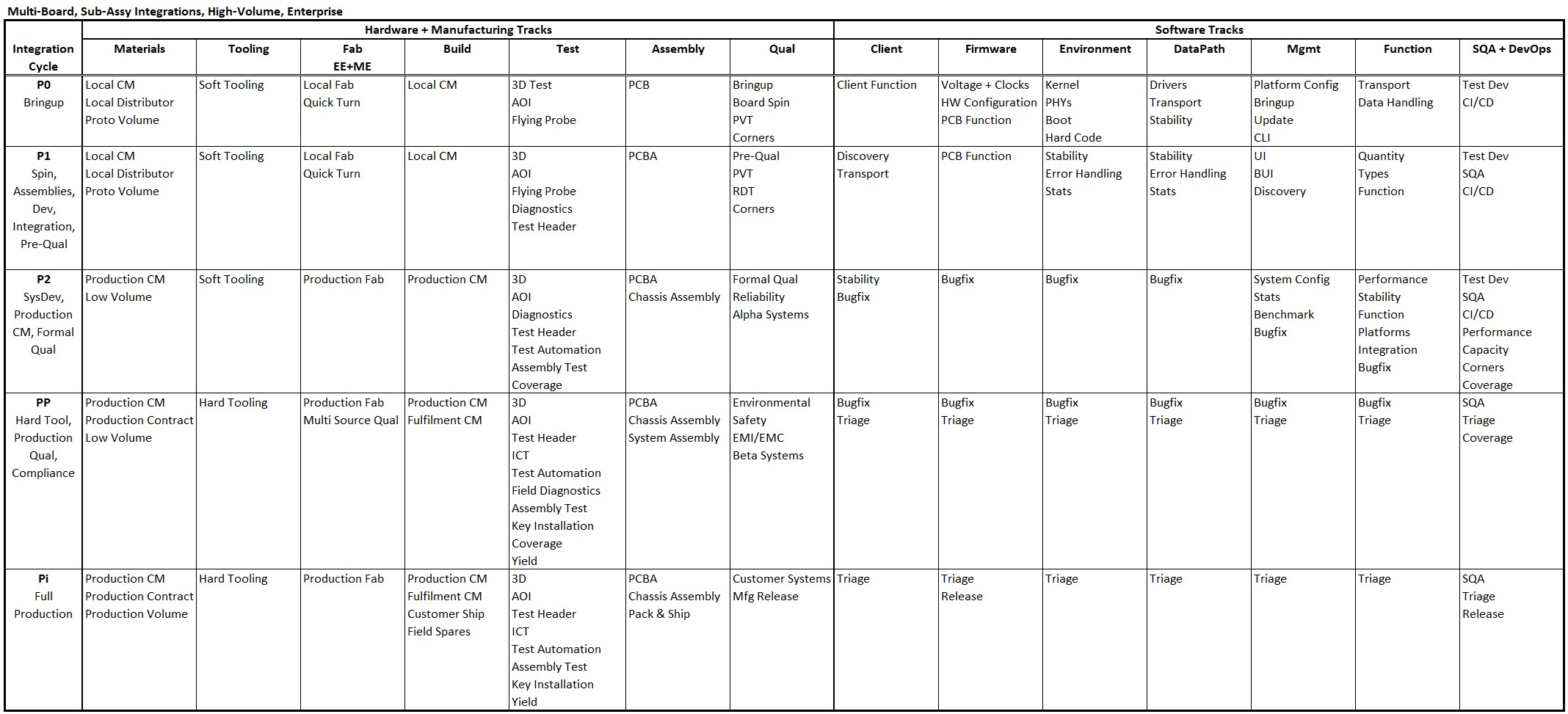
The figure above shows a Table representing major program sequence. This table describing characteristics of Integration Sequences is a critical part of coordinating the multiple development methodologies that may be in use. These develop electronic and mechanical hardware; software from firmware to management and system software; Supply Chain, Manufacturing Operations, Customer Engineering, and Analyst Support. This process simultaneously syncs product deliverables in time and function, satisfies many task deliverables and dependencies, and ratchets progress toward product and Program completion, independent of the multiple technolgoies, methodologies and processes involved. Develop Implementation Plan Addressing The Integration SequencesUsually 5-6 major program Integration Sequence steps are defined in such a table. Each Sequence includes an Integration Point at which deliverables specified by organization are integrated together, creating the major deliverable of the Sequence. This integrated deliverable is distributed and used for major Validation/Test/Compliance/Certification deliverable specified for the Integration Sequence. The figure above illustrates Integration Sequences I have used for system products. Your product may have its own Integration Points different than these, but I expect you can map the concept illustrated. Further examples below. Example Detail
Showing progression of Tracks Through Integration Sequences 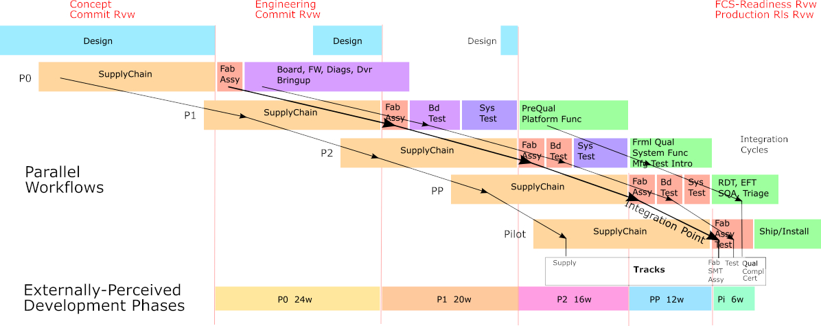
It may seem that the cycles shown are only about hardware development. But Integration Points can help focus software development, too. Furthermore, experience shows that even if development of hardware is included in the Program, about 80% of hardware built (including acquisition of off-the-shelf equipment) is for software development. That hardware is used for software development, distribution, test, certification, and customer exposure; requiring these or similar cycles. Even if new proprietary hardware development is not part of the Program, typically capacity and configurations are required for those software activities. Any internal capacity to be used must be sized, scheduled, and allocated. External hardware for incremental capacity or configurations would need to be sized, scheduled, purchased, and integrated. Some of these activities and spends could be somewhat invisible to the software development organization, if they will be executed by an IT or Lab organization. But the Program would inevitably retain responsibility for overall management including planning and results of these requirements. Build A Quantified Plan Covering All Integration SequencesThe Initial Design Sequence discussed above is shown at top-left in the diagram just above. The Critical Path starts with it, and the Engineering Commit Review kicks off spending and Critical Path through the remainder of the Program. The Critical Path for each Integration Sequence has dependency on completion of design for the upcoming Integration Sequence, plus testing required to validate the prior Integration Sequence. Start building the GANTT with a sequence of Timebox tasks to encompass build and initial test, one for each Integration Sequence. For a system development program, fairly large, experience shows the following. A smaller program likely requires fewer or shorter steps for build, assembly, software and integration, and Manufacturing development.
The Critical Path is shown by the red line running through parts of each Integration Sequence in turn. Program Management needs to identify it, keeping the plan up-to-date, and continuously identifying the CP, and focusing management on optimizing that path, prioritizing issue resolution and provisioning of CP tasks. 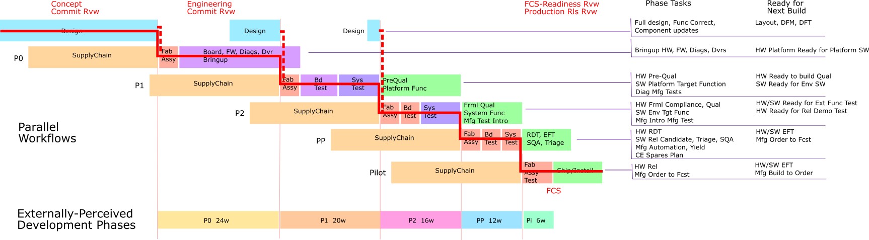
You may notice each sequence in the above example image starts with a long-duration task labeled "SupplyChain". The image actually is to scale from real experience on multiple programs of this size and technology. The SupplyChain duration in the image is driven by materials with long lead-time such as new chips, connectors, PCIe cards, switches, servers etc. The date for the Purchase Order initiating that lead time is calculated BACKWARDS from the Build task using that material. The Build task itself is driven by preceding tasks such as design readiness and test completion from the PRIOR Integration Sequence. Greater detail is shown in the GANTT image below. These illustrate how weeks of time can be taken off the Critical Path by advance planning, and overlapping tasks. It is wise to split first builds from each CM provider site, into an A build and a B build (local P0-A, P0-B, offshore P2-A, P2-B), to check the A build for Dead on Arrival problems before committing remaining material to the B build. Material should be acquired for full A+B quantity, but build A is initiated for perhaps half of units up to 10, to be evaluated before SMT material commit to B build. Quick check of the A build commonly includes shorted power planes, clock issues, wrong sense on high-speed signal, layout-induced timing mis-match on memory data/address traces. For hardware builds that may produce numerous prototype units, usually the GANTT only needs to detail the First-Off units, first to complete assembly and build test. The Program will use those First-Off units to provision subsequent Critical Path tasks. Later units can usually provision non-critical tasks, using slack without affecting anybody's schedule. And you can always add detail to your GANTT for last-off units if you have a situation that does need it. Tasks preceding the irrevocable SMT task in each Integration Sequence should be calculated as reverse dependencies from SMT Start. See Design the Critical Path, Don't Just "Let it Happen". These include component supply chain, fab material, board fab, component acquisition, board-level mechanical part build/acquisition. As a result, they will not be on Critical Path, and can be started independently early to be ready for their associated SMT. Reverse Dependencies are a feature of Microsoft Project; they may need to be manually created in a different GANTT tool. Development of software below the Virtualization Layer should be able to fit into the Integration Sequence overlaps. Interconnect drivers may need partitioning into subsets to achieve this. Software above that layer is more fungible and, if necessary, some function could be prioritized and sequenced, pushed to later internal or external releases as needed to fit requirements of each Integration Sequence. Some higher-level software for an Integration Sequence is not required early in that Sequence. Test of Board, Assembly, and System in each Integration Sequence is broken into two phases in each Integration Sequence: First, test proving the current build will be viable to initiate next-Integration Sequence irrevocable SMT; Second, formal test unlikely to affect irrevocability in the next Sequence. The formal testing can cause component values in the next sequence can be changed, firmware updated, ME parts replaced etc. without violating the next Sequence. Anticipated fab-level rework, however, would force the next Sequence to wait until that can be incorporated before that build. However, that would be unusual beyond P1. Testing following the build viability validation will not gate the next Integration Sequence, so will not be on Critical Path. Some testing from later Sequences (Compliance, Certification etc) may gate final product release, however. Estimate tasks and dependencies, build a GANTT plan consisting of major tasks with dependencies, and with estimated durations. The Critical Path shows on the GANTT. More on Estimation, below. Iterate the plan for best fit of the Critical Path to Program Objectives. Escalate solvable discrepancies, commit the Program to Likely schedule and budget, manage Critical Path to Best Case, and report, escalate, resolve or mitigate deviations as the program progresses. Budget bloat can be somewhat controlled by building DevKit systems for most development work. Most developers don't need the full capabilities of the product, and a "stripped-down" configuration will be sufficient. So DevKit configurations include limited processors, memory, failover, scalability, LAN (use VLANs), displays, etc. More fully-configured systems can be built for SQA, Compliance, and internal and external Alpha and Beta systems, and can be used for corner testing of scalability, fault-tolerance, capacity etc. The result of the Timebox infrastructure, with detail for each Timeboxed Sequence of the Supply Chain acquisition, Board/Assembly/System build and test, and Formal test sequence defining each Integration Sequence, should be a plan consistent with the overlapped image above. When the Critical Path tasks have been incorporated into the GANTT, the Timebox task structure may optionally be removed. That could shorten that part of the Integration Sequence; or if GANTT tasks require more time in an Integration Sequence, they will drive the planned time for the critical path of that Sequence. GANTT Quantification should specify major staffing. This might be at the levels such as: Corporation, CM Local ("CM" - "Contract Manufacturer", typically offshore with onshore limited capability), CM Offshore, CM Production Site. Associate a calendar with each. No need to identify days off and weekends, you can't identify that level of accuracy, and you can manage around it in real time. But you need national calendars that identify major effort deviations such as Lunar New Year, Golden Week, Christmas, Thanksgiving. Also, Asian sites typically work a 6-day week vs. 5-day weeks in Western sites. Size tasks in weeks, duration reflecting local weekly workdays. Below is a detail image showing a piece of a program GANTT plan implementing the above image. Note the Critical Path indicated in red. Dates for some predecessor Supply Chain tasks are calculated backward in time, as above, from the irrevocable critical path Build task. 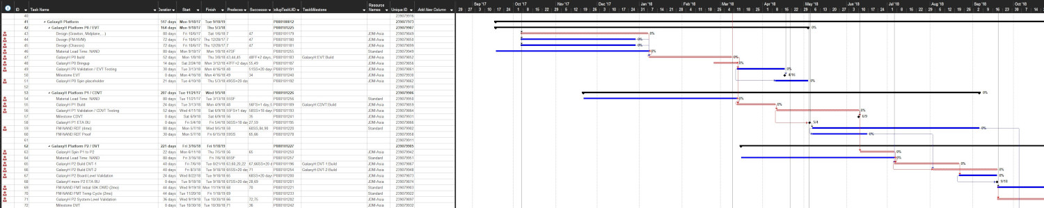
From MS Project, an Excel file can be exported using VBA containing fields chosen to represent the Program. That file is link-able with logistics Tables via field TaskMilestone inserted into the MS Project file. Templates (free) are provided from my website referenced at the end of this Article. How To Estimate DurationsSome tasks are easier to estimate than others.
Wherever possible, keep difficult-to-estimate tasks off the Critical Path. Ideally, bring up new stuff on a context of older stuff, or on scaffolding. That is not always possible, but check your cases, most parts of a program will not gate irrevocable tasks. You might also push function among releases to support the program as a whole. You could plan based on "how long do we have for this".
Basic estimating - References Estimation Methods
Keep slack out of task estimates, they just pad estimates resulting in a false understanding of the program. Keep slack as a variable that can be used by the Program Manager to alleviate real problems when they occur. Don't give that away before you even start. Iterate the schedule and material plan to meet objectives of both time and cost, until met or until immutable barriers are identified and explainable. Note that prototype spending spikes at Build tasks, so needs to fit into organizational finance. You may find at first that the organization has not considered spikes in spending, or the need to issue purchase orders in a quarter earlier than material receipt, due to lead time. You may need new agreement on rules for capitalization (lifetime, cost; use of material in destructive or damaging test). Get agreement on schedule timing, and spending amounts and timing profile. Initial Estimations: Bottom-Up, Or Top-Down?Time and Money are topics on which the Program Manager must lead. Bottom-up planning on these as a first effort is a path to failure; better to go in with a Plan to be evolved. Bottom-up planning usually encounters planners including invisible slack; extra material; durations likely to be unnecessarily pessimistic (or optimistic!); Trade-offs, especially if cross-domain, haven't been well evaluated; critical-path not known or evaluated. Schedule or Budget planned and executed bottom-up are unlikely to contract later - nothing adds decision criteria as much as Budget and Schedule that fit the business plan. As Program Manager, first determine "how long do we have to do this", go to the Team with a plan that breaks up the work to fit. Then review and update with the Team principals, continuing with all participants driving toward agreed business objectives. To fit available time+resources+cost, you may be able to shift work (features, non-critical path testing) out (to avoid delay) or in (for opportunity or improved result) among Integration Sequences. Forgiveness or permission for more time or budget vs. agreed objectives is more likely if you can describe the problem and mitigations tried. Time is the most valuable resource, more valuable than money. Tasks that are NOT Critical Path have more flexibility on duration and start planning; use their slack if changing work flow, to help the Critical Path. If a critical path item is delayed, attempt to remove that work from the critical path, and replace it there with a work-around to maintain critical path progress. Keep the whole program working, not waiting for some uncertain resolution. Then when the issue with the delayed item is resolved, insert it back to use on the critical path. You may find that such a re-fit need not be universal, and can be focused to supply only work needing specifics of that particular item. Break Critical-Path tasks if possible into Critical and non-Critical segments, and allow only the Critical portion on Critical Path. For example, after a Build, identify tests REQUIRED prior to irrevocable material commit in the NEXT Integration Sequence build tasks as a dependency for that commit. Testing of the previous Integration Sequence usually continues beyond that and may drive dependent tasks that can be revoked, reworked, repeated in later Integration Sequences. Design The Critical Path, Don't Just "Let It Happen"Overlap work wherever possible based on dependencies and staffing.
The net of this construction creates the Critical Path optimized across overlapped Integration Sequences, as shown in the images above.
How Does Accuracy Improve Over Time?Accuracy of the schedule plan improves as the Program progresses. Factors include:
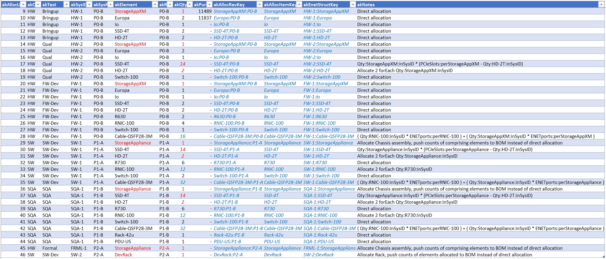
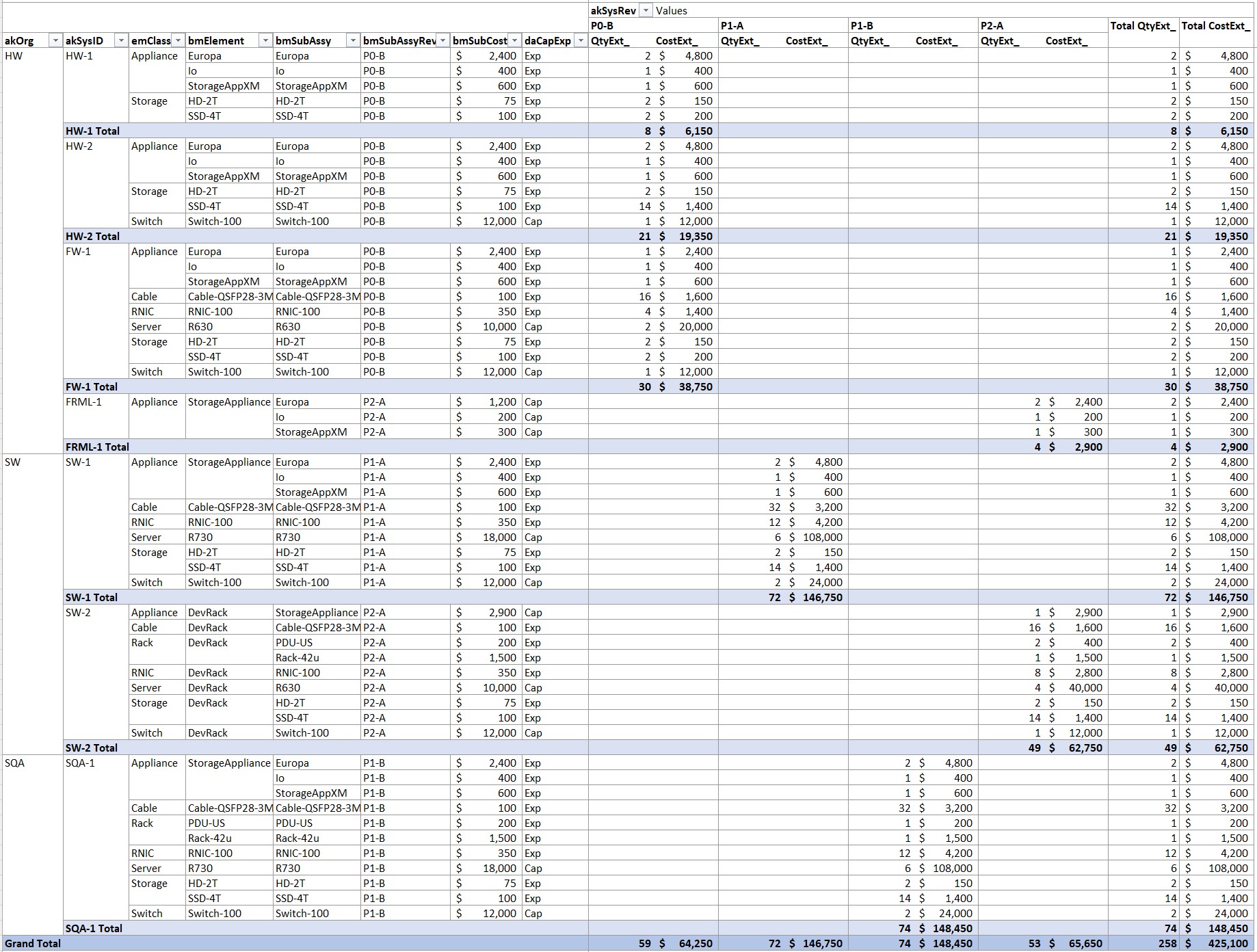
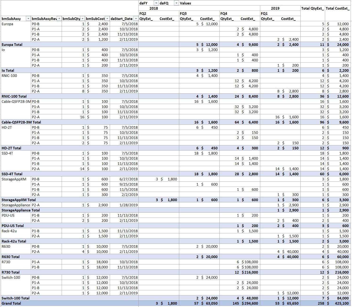
Attach Materials And Therefore Finance To The Integration Sequence PERT PlanBroaden the plan beyond timing to include Resources, Logistics and Finance. Resources include Material (quantities, item cost), Staff, and Licenses. Logistics include material Acquisition (RFQ, Quote, PO, Lead Time, Delivery, Inventory, Marshalling, Build), Tracking, Distribution. Finance includes costs (schedule time of PO vs Lead Time, Material receipt, Pay Date), and expense/capitalization determination. Overall, Schedule drives Logistics, and Logistics drives Finance. If you use Microsoft Project you can export the GANTT plan to an Excel or XML table that can be JOINed with other Tables (via a linked database environment or Excel PowerQuery) itemizing materials and expenses to be associated with milestones in each Integration Sequence. This is automated in the PowerOpI tools (free) available on my website www.softtoyssoftware.com. The website also provides many descriptions, examples, code samples, links and resources to help you build your own tooling. Materials and Finance Tables are discussed in article Advice for Program Managers: 4-Program Management Specialization: System Programs Phased Methodology and illustrated in Organizing Program Communication. Images of example relevant Material and Finance Tables The following Tables, SQL, Reports and Images are taken from tools described, and available FREE, from my website softtoyssoftware.com. The site also describes underlying methodology and tooling for your own design. Allocation: Represents use, configuration, Integration Cycle, and quantity. Includes key-fields for local cost aggregation and JOINs to related tables including Program BOM and element data reference.
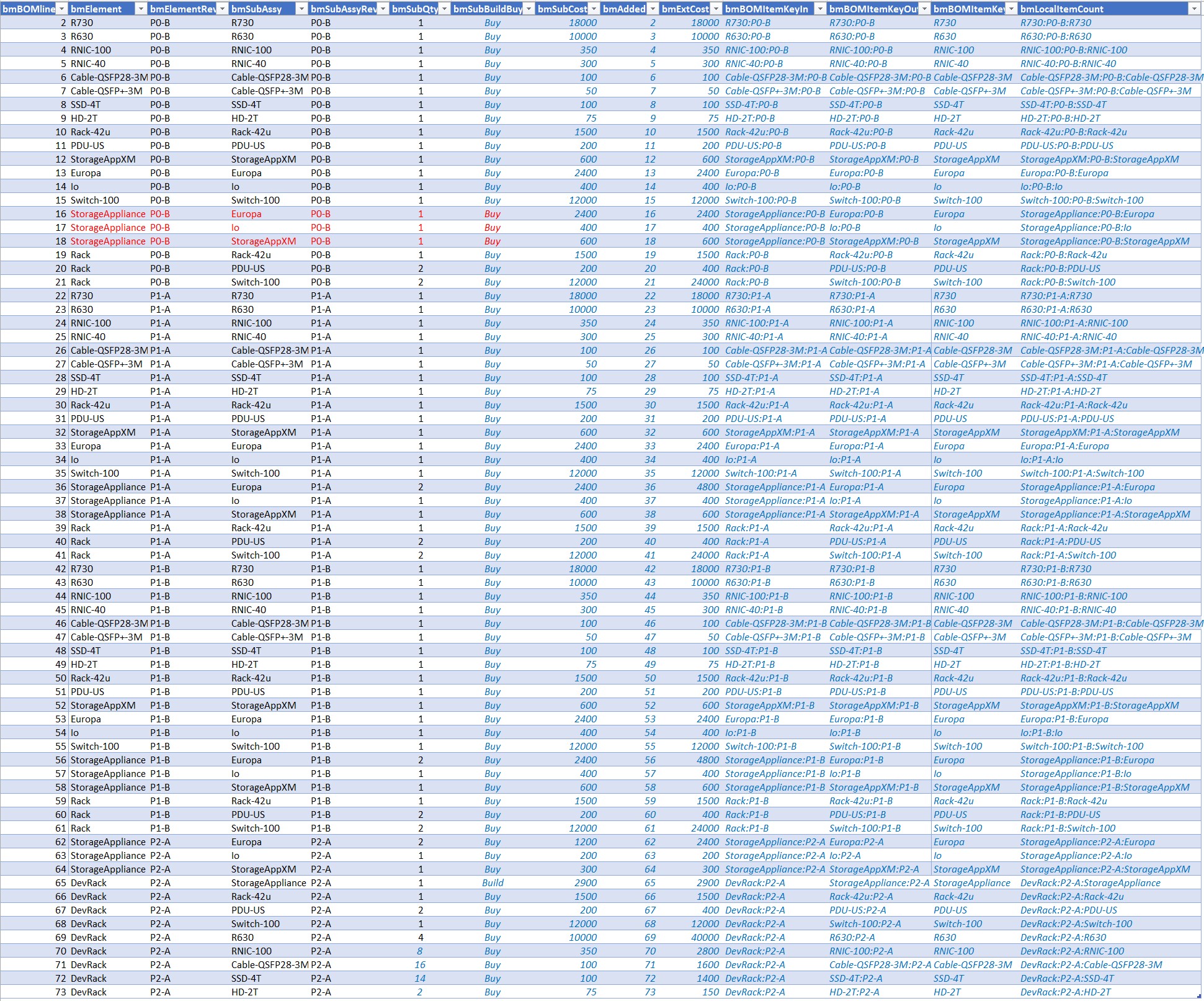
Program BOM: Represents a Product Tree structure including components, built items, assemblies, and systems, for each Integration Cycle/Phase. Includes key-fields for JOIN.
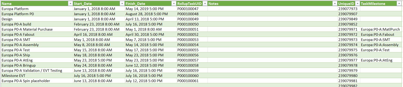
MS Project Import: Raw data import from MS Project for task data. In the MS Project file, field “TaskMilestone” has been added and populated to provide a key-field for JOINs to related tables.
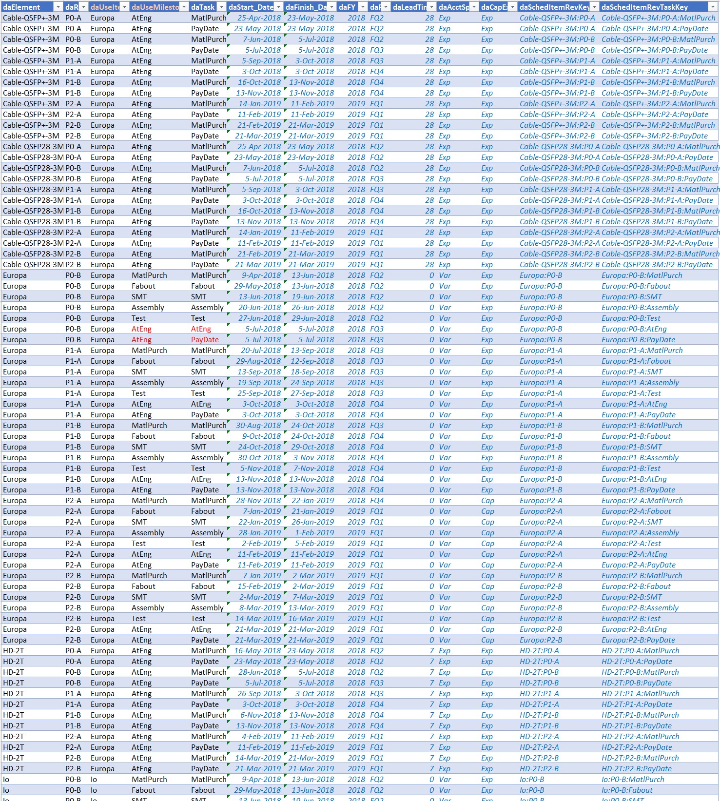
Dates: Normalized table associates dates from MS Project import table with Program BOM items. This table implements date aliasing to support purchased items not represented in MS Project that can be synced to builds. This simplifies scheduling of those items that do not need task sequencing. Key fields for JOIN are included in the table.
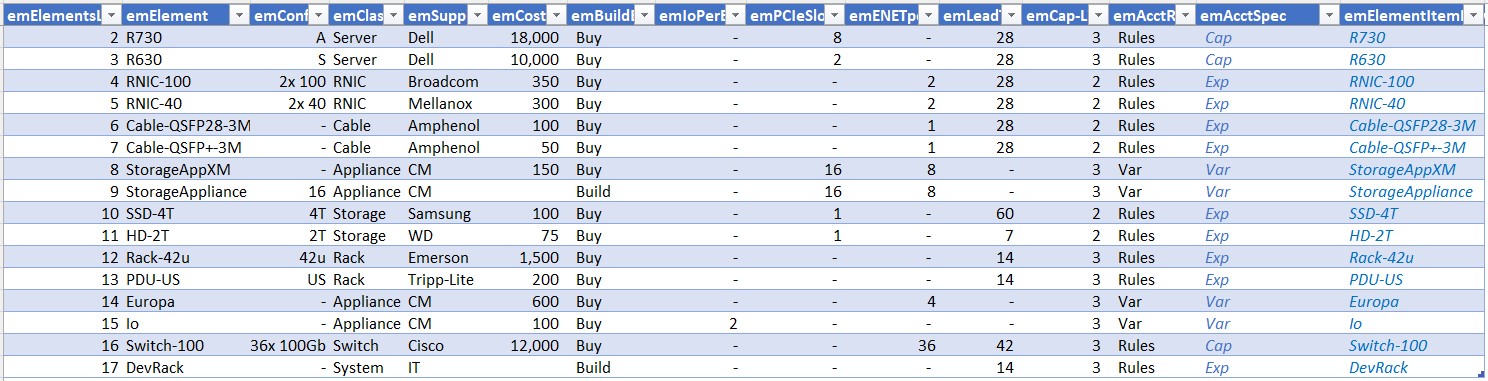
Element Data: Raw data for each component, element, assembly or system item planned. Configuration detail, cost, supplier, distributor, slots, ports, cap/expense rules, lead-time etc. – any item data to be included in reports of affect rollup in other tables. Includes key-field for JOIN.
VLSI Die Logistics: Tables can manage planned and actual die allocation among wafer lots. A table for fabout and build planning would include dates and quantities for tapeout, substrate fab, metal fab, test probe and packaging substrate including planning for any deferral of metalization, probe test, and packaging. Probe test count could be recorded to manage probe limit. A table for wafer planning would organize die allocation for each lot by wafer, to allocate die usage among process-corners. This is particularly useful for planning corner lots exposing the chip design to multiple mixed-domain process variations (e.g. SFFT slow-fast-typical), and provisioning operational use of yielded die. Fields for test status by die can manage process-corner yield, and selection for yielded-die allocation to packaging and product test. Data specifics for these chips, managed as part of an overall Program and used within program product assemblies, can be added as components into tblBOM above. Use of specific process variations can be accomplished by appropriate chip naming in the wafer management table above or by other linking key construction. Chip dates can be added into the overall GANTT, or linked into tblDates. tblElements can include chip entries for cost, supplier, power, etc. Purchase order data for chips can be included into tblPurchReq, with Purchase Order number added into tblAlloc. This methodology of adding tables to accommodate specifics managing creation of use of VLSI technology within a Program, generalizes to make it possible to add other technologies requiring specific management into the Program Plan. These Tables can be joined by SQL like this:
/* QUERY Build Plan DB Tables */
SET ANSI_NULLS ON
SET QUOTED_IDENTIFIER ON

  SELECT [SQLServerRemoteDB].[dbo].[xlAlloc].*, [SQLServerRemoteDB].[dbo].[xlBOM].*,
    [SQLServerRemoteDB].[dbo].[xlDates].*, [SQLServerRemoteDB].[dbo].[xlBuilds].*,
    [SQLServerRemoteDB].[dbo].[xlElements].*, [SQLServerRemoteDB].[dbo].[xlPurchReq].*,
    [SQLServerRemoteDB].[dbo].[xlAlloc].[akQty] *
        [SQLServerRemoteDB].[dbo].[xlBOM].[bmSubQty]
        AS QtyExt,
    [SQLServerRemoteDB].[dbo].[xlAlloc].[akQty] *
        [SQLServerRemoteDB].[dbo].[xlBOM].[bmSubQty] *
        [SQLServerRemoteDB].[dbo].[xlBOM].[bmSubCost] AS CostExt
  FROM [SQLServerRemoteDB].[dbo].[xlAlloc]
  LEFT OUTER JOIN [SQLServerRemoteDB].[dbo].[xlBOM] ON
    [SQLServerRemoteDB].[dbo].[xlAlloc].[akAllocRevKey] =
    [SQLServerRemoteDB].[dbo].[xlBOM].[bmBOMItemKeyIn]
  LEFT OUTER JOIN [SQLServerRemoteDB].[dbo].[xlDates] ON
    [SQLServerRemoteDB].[dbo].[xlBOM].[bmBOMItemKeyOut] =
    [SQLServerRemoteDB].[dbo].[xlDates].[daSchedItemRevKey]
  LEFT OUTER JOIN [SQLServerRemoteDB].[dbo].[xlBuilds] ON
    [SQLServerRemoteDB].[dbo].[xlDates].[daSchedItemRevKey] =
    [SQLServerRemoteDB].[dbo].[xlBuilds].[bdBuildRevKey]
  LEFT OUTER JOIN [SQLServerRemoteDB].[dbo].[xlElements] ON
    [SQLServerRemoteDB].[dbo].[xlBOM].[bmBOMItemKey] =
    [SQLServerRemoteDB].[dbo].[xlElements].[emElementItemKey]
  LEFT OUTER JOIN [SQLServerRemoteDB].[dbo].[xlPurchReq] ON
    CAST([SQLServerRemoteDB].[dbo].[xlAlloc].[akPurchReq] AS VARCHAR) =
    CAST([SQLServerRemoteDB].[dbo].[xlPurchReq].[prPurchReq] AS VARCHAR);
SQL shown is targeted to SQL Server; you would use syntax consistent with your chosen Database environment. To Join Tables, PowerOpI Tools support
My website describes how to use these database environments with Excel (Tables and Reports), Project (GANTT Schedule), and Visio (Images). Images of example relevant Material and Finance Reports A report summarizing equipment allocated to Development, by organization with equipment detail, its use (indicated by named SysID), its targeted build in an Integration Cycle, then its quantity, cost, and capital/expense status.
A report for Operations listing dates to plan and execute board builds within each Prototype Cycle; and assembly, integration, and test. The report results in a table of many dates, so Excel conditional formatting is used to highlight and alert for actions upcoming shortly, and for actions that should have been recently completed. Dates for operations completed further back in time are shown muted so that upcoming operations will be shown more prominently.
A report for Finance showing all expenditures summarized by item, and by Fiscal Date. Dates in other reports for Operational tasks are shown using calendar dates but for Financial reports, dates are translated to Fiscal dates within the Excel PM tool. This translation often falls to Program Management. Typically Finance uses many reports for planning and actuals, for expense and capital items, for cashflow timing, and many more.
A report planning Purchase Orders, and tracking progress of items purchased. Purchase Orders are planned to start in time for item deliveries for builds - dates for built items are shown in the Operations report above. And it doesn’t make sense to start a build unless necessary items have been delivered. Once delivered, status tracking of physical storage and distribution of items helps prevent “lost” items from impeding progress implementing the program plan.
Example images derived from Program data illustrated above: Images provide intuitive vision and understanding of where we are and where we're going, both short-term and long-term, to all levels of an organization. Images displayed here are all driven from the GANTT. 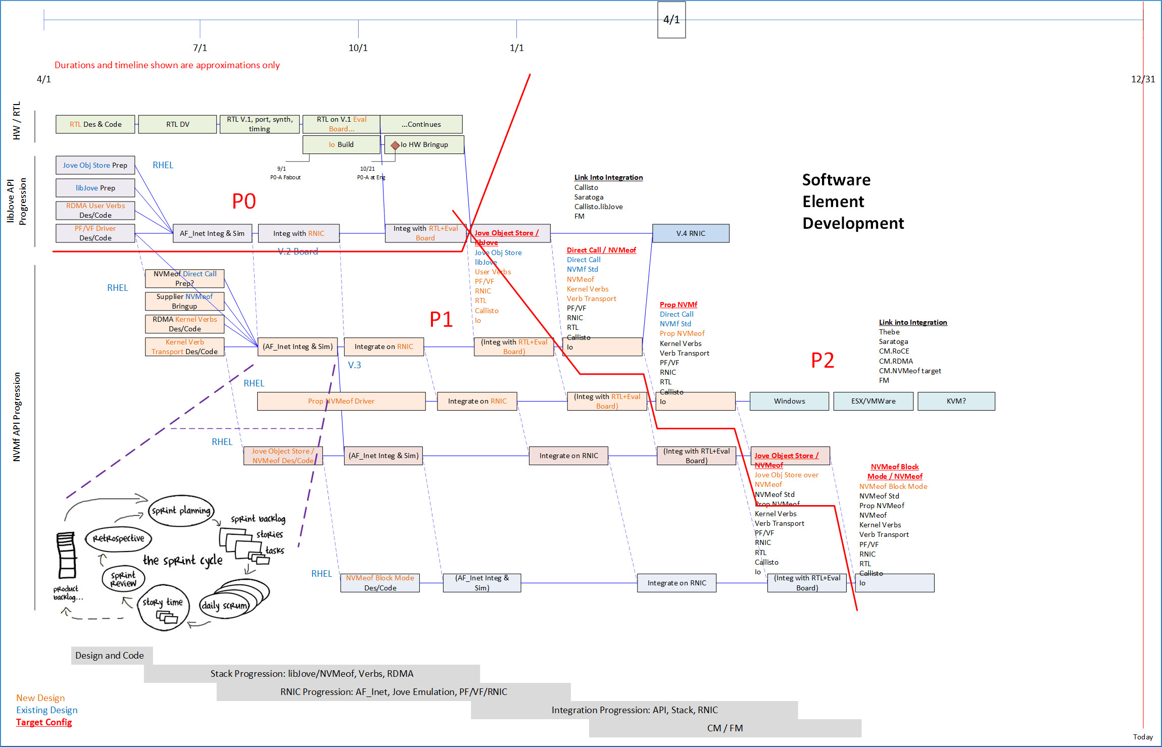
Operationally: Use The Plan - AdaptivelyDid you think you can make a plan, execute it, and it will stay fixed while you do that? Keep plan current in real time. Make real-time estimates. - Use Automation to make updates possible with reporting/guidance available in short time with minimized labor.
The Program Manager, and all Program team members, should use representations of the Program Plan to communicate: up, down, across, throughout the Program and all participating organizations. Communicate current standing relative to ultimate objectives, and on current and shortly upcoming tasks; as relevant to participants in the dialogue. Collect ideas, adopt if appropriate and propagate through the plan. Collect current and upcoming issues, work out reaction and propagate through the plan. Use automation of the Plan to facilitate this. The article on this site, Organizing Program Communication, discusses many ways of facilitating communication about the Program in all dimensions. 
The schedule is in fact always wrong. Let's state that more usefully: The schedule is always approximate, stating The Best Known Path From Here in a way that is useful for coordinating subsequent tasks and milestones. It's all a matter of degree: remember, the "schedule" contains tasks with estimated times (which is where most error can occur), plus sequencing of tasks driven by dependencies, which is usually pretty accurate. So update it continually toward correctness. That alone will add value to the project, and the schedule will become more and more accurate as data is corrected, as operational changes are incorporated, and as uncertainties are resolved and reflected in the plan. Identify risks that the plan illuminates - at Planning, During Execution. Report the risks in advance, and handle them. Identify decision points, get homework done in advance, get the decisions made on time to avoid unforced error. Monitor for risks. Practice Avoidance, Mitigation, Alternatives, Solution, Operational change. Take seriously tasks for Validation, SQA, Field Test with Multiple Customer environment exposure. A release sequence might consist of full-function and SQA'ed preview release, then Certified Release inclusive of exposure, Compliance and Certification. Certified release could be further broken into multiple release branches targeted to customer classes, perhaps geographic or consumer/enterprise, and released over a time sequence to achieve incremental customer environment exposure while avoiding broad mishap due to product defect detected as exposure broadens. Avoid field-level disaster - don't sacrifice product integrity in favor of early delivery to live customer use. Implement Agile Mindset: Be open to necessary or opportunistic change, be able to Incorporate Change. But: don't let Agility derail the Program or customer.
In Short: Execute The Plan, Use Agility To Advantage
Further Reading: Core Program Quantitative Structure for System ProgramsAdvice for Program Managers: The Blog Series1-Program Management Opportunity Introduces a vision and framework for development of Program Managers and PMO, for Program Management specialization to its environment, and for improved effectiveness and integration of PM with organization operational management. 2-Program Management Career Path Describes career path thinking for Program Managers including sourcing, progression, advancement, and connection with organizational management. 3-Program Management Career Skills Career path thinking for Program Managers including skills and behaviors that develop Program Manager capabilities and leadership and pave the way toward advancement. 4-Program Management Specialization: System Programs Phased Methodology PM Best Practices and Core Program Structure for Hybrid integrated system programs using Phased HW – Agile SW, mixed-technologies. Full-Program agility via automated plan tools with continuous plan update. The Series also solicits contributions to this Blog site, to extend coverage of PM Best Practices and Core Program Structure to a broadening set of Specializations. PMO behavior to achieve Program Management effectiveness specialized to its environment managing PM practices in the organization, including PM development and advancement and connection with organizational management. 6-Quantified Agile for Hardware Program Quantification applied to Phased and Agile methodologies to deal with organizational quantitative requirements. More Articles by this AuthorThree Levels of Program Management Guiding Principles for Program Management Action, Program Quantification, and Leverage Through Tooling. Organizing Program Communication Program Management depends on effective communication. Design Program communication paths for everyone throughout the Program. Database Platforms for Program Management Logistics Logistics Tool extended, using SQL Server and MS Access with MS Excel and PowerQuery. Logistics Tool using MS Excel Power Query. Tool methodology for agility with continuous plan update: Program BOM, Tie to Dates, Builds, Element data. Structure Program with Parallel Phasing. Describes coordination of EE/ME, FW, Test, Supply/CM, Driver/Kernel, Transport, Management. Scheduling, Integration points, scaffolding, and starting work. Hybrid Program Cross-Domain Coordination of development frameworks, including Phased and Agile/Scrum where appropriate, via integration points and scaffolding. Software Integration Sequence and Dependency Planning. Problem Statement. PM responsibility for Program Management drive throughout an organization, also includes schedule, budget, integration, critical path, logistics. Planning work structure for a Program, and using the plan effectively. AI effects on current and future lifestyles. Personal strategies for proactive and defensive use of AI. Using Iterative Thinking to solve big problems and complex logistics. AI resources to help adopt AI into your lifestyle. PM/PMO role identifying, evaluating, and propagating AI Best-Practices through an organization. Development Frameworks directly affect business fundamentals of the organization. Positioning PMO for better business results. AI in the physical world. Link To Free Tools To Manage Schedule, Logistics, And FinanceAuthor's www.softtoyssoftware.com website with articles on Program Management and Program quantification tooling using Excel, MS Project, and MS Visio with SQL databases PowerQuery, SQL Server, and MS Access. Articles describe how you can use tools available from the website, or develop these capabilities yourself using commonly available tools. Tools available from this website are free. They can handle small to large programs, limited only by your imagination. Using the included Program Template to envision, organize, plan, and run a large program puts me in mind of unleashing a Roman Legion to a sure outcome. Veni, Vidi, Vici! – Julius Caesar.
Credits Image(s) used under license from Shutterstock.com. Attribution: elenabsl / Shutterstock.com My website: www.softtoyssoftware.com Copyright © 2024 Richard M. Bixler All rights reserved |